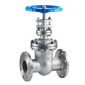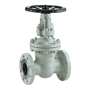

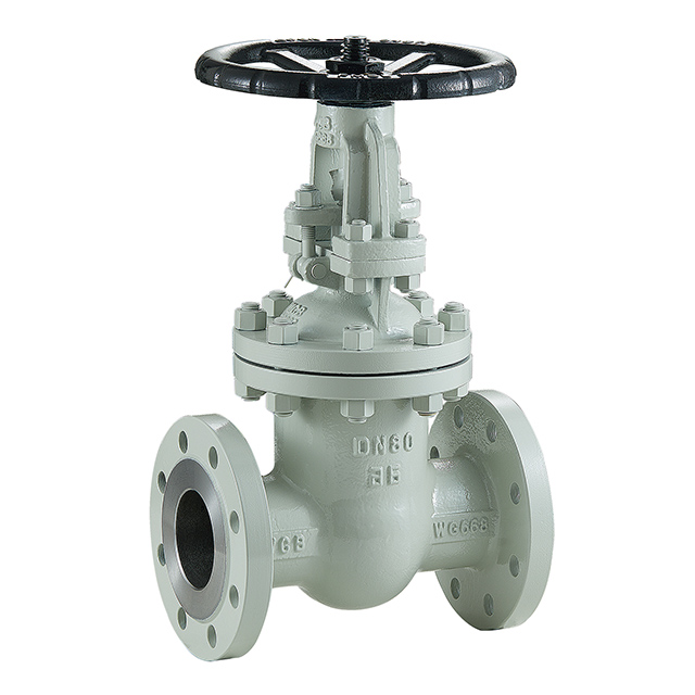
Gate valves consists of three main parts.. body, bonnet, and trim. The body is generally connected to other equipment by means of flanged, screwed or welded connections. The bonnet, which containing the moving parts, is attached to the body, usually with bolts, to permit maintenance. The valve trim consists of the stem, the gate, the disc or wedge and the seat rings.
Disks of a Gate valve
Gate valves are available with different disks or wedges. Ranging of the Gate valves is usually made by the type of wedge used.
The most common were..
-
Solid wedge is the most commonly used disk by its simplicity and strength.
A valve with this type of wedge can be installed in each position and it is suitable for almost all liquids. The solid wedge is a single-piece solid construction, and is practically for turbulent flow. -
Flexible wedge is a one-piece disc with a cut around the perimeter to improve the ability to correct mistakes or changes in the angle between the seats.
The reduction will vary in size, shape and depth. A shallow, narrow cut gives little flexibility but retains strength.
A deeper and wider cut, or cast-in recess, leaves little material in the middle, which allows more flexibility, but compromises strength. - Split wedge is self-adjusting and selfaligning to both seats sides. This wedge type consists of two-piece construction which seats between the tapered seats in the valve body. This type of wedge is suitable for the treatment of non-condensing gases and liquids at normal temperatures, particularly corrosive liquids.
- Stem of a Gate valve
-
The stem, which connects the handwheel and disk with each other, is responsible for the proper positioning of the disk. Stems are usually forged, and connected to the disk by threaded or other techniques. To prevent leakage, in the area of the seal, a fine surface finish of the stem is necessary.
Gate valves are classified as either..
- Rising Stem
- Non Rising Stem
For a valve of the Rising Stem type, the stem will rise above the handwheel if the valve is opened. This happens, because the stem is threaded and mated with the bushing threads of a Yoke. A Yoke is an integral part from a Rising Stem valve and is mounted to the Bonnet.
For a valve of the non Rising Stem type, there is no upward stem movement if the valve is opened. The stem is threaded into the disk. As the handwheel on the stem is rotated, the disk travels up or down the stem on the threads while the stem remains vertically stationary.
Below you will find links to detailed (large) images of both stem types.
Seats of a Gate valve
Seats for Gate valves are either provided integral with the valve body or in a seat ring type of construction. Seat ring construction provides seats which are either threaded into position or are pressed into position and seal welded to the valve body. The latter form of construction is recommended for higher temperature service.
Integral seats provide a seat of the same material of construction as the valve body while the pressed-in or threaded-in seats permit variation. Rings with hard facings may be supplied for the application where they are required.
Advantages and Disadvantages of Gate valves
Advantages..
- Good shutoff features
- Gate valves are bidirectional and therefore they can be used in two directions
- Pressure loss through the valve is minimal
Disadvantages..
- They can not be quickly opened or closed
- Gate valves are not suitable for regulate or throttle flow
- They are sensitive to vibration in the open state
-
Main Connection Dimensions 型号
Type公 称 通 径
DM(mm)Dimension(mm) L D D1 D2 b-f Z-Φd H D0
Z41W-16
Z541W-16
Z941W-1615 130 100 65 45 14-2 4-Φ14 185 120 20 150 110 75 55 14-2 4-Φ14 200 120 25 160 120 85 65 14-2 4-Φ14 225 140 32 180 140 100 78 16-2 4-Φ18 275 160 40 200 150 110 85 16-3 4-Φ18 295 200 50 250 165 125 100 16-3 4-Φ18 350 220 65 265 185 145 120 18-3 4-Φ18 370 240 80 280 200 160 135 20-3 8-Φ18 390 280 100 300 220 180 155 20-3 8-Φ18 435 300 125 325 250 210 185 22-3 8-Φ18 520 320 150 350 285 240 210 24-3 8-Φ23 610 350 200 400 340 295 265 26-3 12-Φ23 785 400 250 450 405 355 320 30-3 12-Φ25 930 450 300 500 460 410 375 30-4 12-Φ25 1080 500 350 550 520 470 435 34-3 16-Φ25 1200 550 400 600 580 525 485 36-4 16-Φ30 1400 600
450
650
640
585
545
40-420-Φ30
1500
650500 700 715 650 608 44-4 20-Φ34 1630 700 600 800 840 770 718 48-5 20-Φ41 1830 750 700 900 910 840 788 50-5 24-Φ41 1930 800 800 1000 1020 950 898 52-5 24-Φ41 2030 850 900 1100 1120 1050 998 54-5 28-Φ41 2130 900 1000 1200 1255 1070 1110 56-5 28-Φ48 2230 950